This post is still Work In Progress
This post is mostly written in hindsight, so you can safely assume that many of the early problems and issues have been forgotten…
The point of this project was to build a heater for one of the those “blow up” pools that you can get to keep the kids happy and cool in the summer. They need to be cold enough to cool the participants down, but not so cold they don’t want to get in or stay in. I should point out that I’m in the south of the UK.
The pool in question is a standard circular 10ft pool, made of flexible plastic, with an inflatable rim. It holds about 4000 litres of water, and comes with a filter and associated pump (mains powered).
The basic plan is pretty simple:
- Build a solar water heater out of black pipe.
- Pump the pool water through the heater.
The basic principle of the solar water heater is that sunlight hits the black pipe and the heat is absorbed. The water flows through the pipe and absorbs the heat, moving it into the volume of the pool. There are a couple of ways to make this more efficient:
- Increase surface area – so we can place the pipes on top of a surface that absorbs heat and conducts it to the pipes.
- Reduce heat loss – so a transparent cover to let in the heat but prevent air/wind cooling, and some insulation between whatever is absorbing the heat and the box it is in.
In “proper” solar thermal panels (https://en.wikipedia.org/wiki/Solar_water_heating), they use evacuated tubes – which are very efficient… I can’t quite run to that sort of thing.
The other thing of course is to try and build it all “DIY” (cos it’s more fun) and to keep things as cheap as possible.
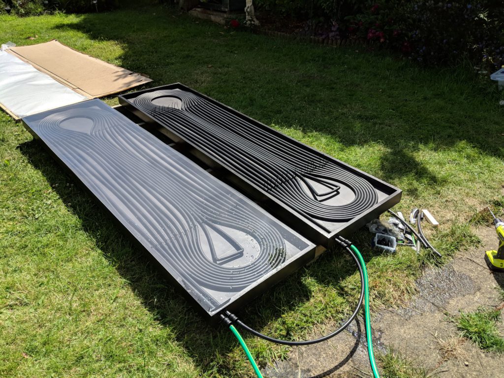
The Box
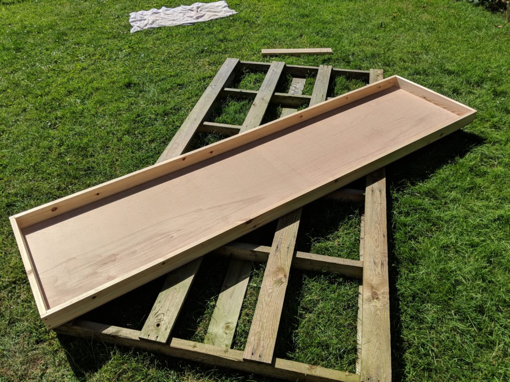
I made the box out of wood, with marine ply for the base. I treated and painted it (black of course) so that it would survive a bit longer exposed to nature. It’s important to remember to put some drainage holes in…
The two boxes were made using
- Structural Hardwood Plywood 2440mm x 1220mm x 9mm for the bases.
- Redwood Planed Timber Standard 25mm x 75mm Finished Size 20.5mm x 69mm for the sides.

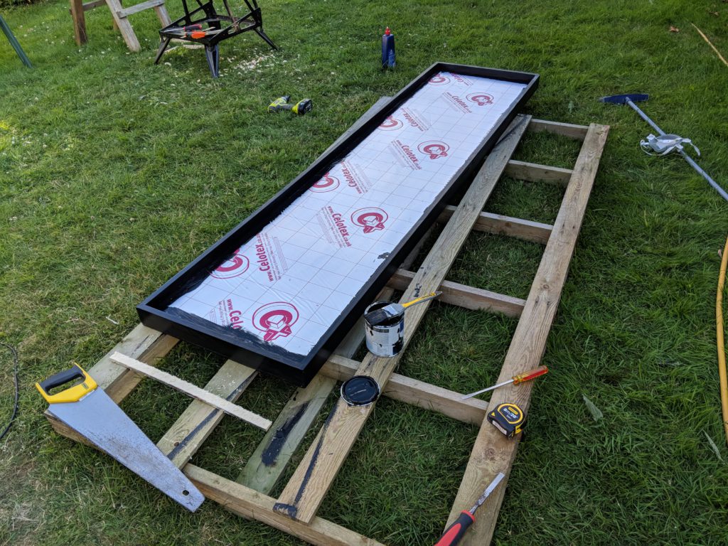
Insulation
I used Celotex PL3025 High Performance Thermal Laminate Insulation Board Plasterboard 2400mm x 1200mm x 25mm – this was enough for two units.
The Heat Spreader
I ordered a piece of aluminum sheeting cut to the size of the box, and sprayed it matt black with high temperature paint (sort of thing you would paint a barbecue with). I got my mine from Aluminum Warehouse
Length (mm) 2388 Width (mm) 558 Grade 1050AH14 Thickness 1.5 mm
I was probably overly cautious with the tolerance, but it fitted well.
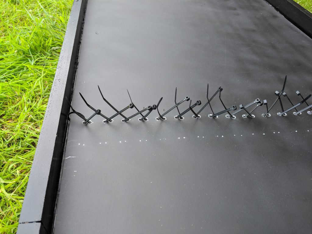
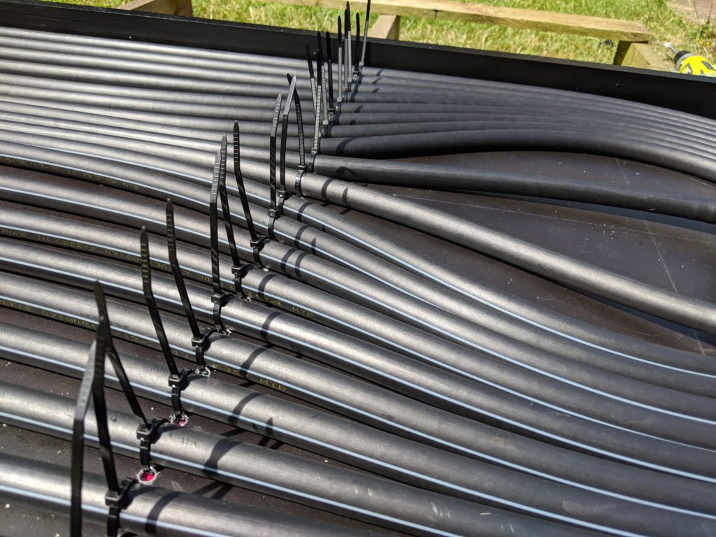
The heat spreader is also exceedingly useful for holding the pipe in place, I drilled a number of holes and used small cable ties for this. I also used some smaller aluminum strips (Size mm: 300 x 30 x 0.9) to hold things in place.
The Pipe
A pretty crucial part of the puzzle, I went for Black LDPE pipe, 13mm, essentially garden irrigation pipe. Incidentally, also the same inner diameter as a standard hosepipe. You can get a 50m reel of it for a reasonable amount from an irrigation supplier. I got much of this from Water Irrigation alongside a number of fittings.
Each of my heaters (I originally made a test unit, then two larger ones at a higher quality) needed about 25m of pipe. I ended up only really needing one – it turned out the three of them together was a little too much.
One thing I was conscious of was that LDPE is good at 80C, OK at 90C for a little while, but above that it will struggle… as a result I was worried that if the water wasn’t kept moving there could be a fairly major failure.
Another thing to be cautious of with LDPE pipe is that it’s quite easy to kink – which is not good. It’s also plastic, and will break-down over time releasing methane and ethylene – so probably not the most climate friendly product. Here, I’m mentally offsetting that with the reduction in energy use as compared to an electric heater for the pool.
On the plus side it’s cheap, easily obtainable, can be used for other projects (like garden irrigation) and easy to cut.
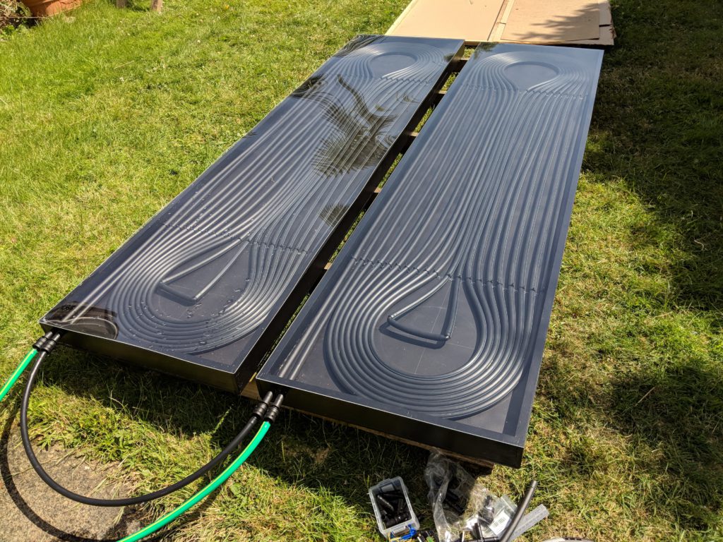
Getting the pipe into the box, and keeping it in place, was not as easy as I had expected… It necessary to be quite careful with the bend radius, as squashing the pipe or kinking it would not be good. In the end, having a good idea of the lengths I needed, I started two pipes in parallel working from the outside in, and then joined them in the center.
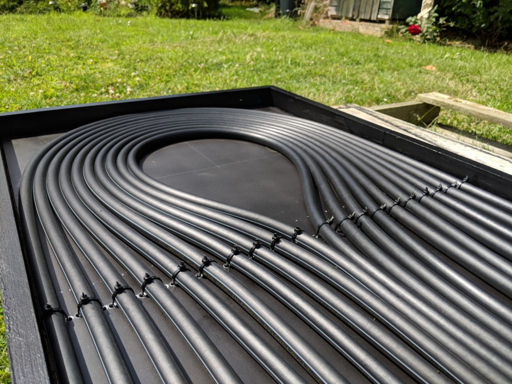
It’s worth noting that the image above was before I added the metal strips to hold the loops in place better. I will add a photo of these…
The Cover
I ordered a piece of clear Perspex® acrylic sheet, cut to size, from Cut Plastic Sheeting
- Thickness: 2.0 mm
- Shape: Rectangle
- Finish: None
- Rounded Corners: No
- Drilled Holes: No
- Height: 2390mm
- Width: 560mm
The Pump
The first iteration of the project had all three units mounted on a low (conservatory) roof. This created a head of over 3 metres, and this was overcome using an old central heating pump. Eventually this failed…
The new more “eco” solution, uses a small 12V water pump found on eBay, which is powered using a small Solar PV panel (and a few other bits). I think it was rated for about 800l per hour. The potential head is a lot lower (untested) but this instance of the solution is a single unit, placed on the ground at an angle (rather than on a roof). I like this a lot better as the heater solution is truly “off grid” and entirely solar powered (both heating and circulation).
Solar PV Panel
Got a small 20W flexible panel with charger and a few other extras from eBay. It turned out the panel wasn’t quite up to the job, but the other bits were useful. I will use it in another project I’m sure. I replaced it with a larger panel, but kept the charger unit.

I’m now using a larger 40W panel, which has been perfect even on cloudy days.
It’s worth mentioning I had to get a small lead acid battery to make it all work. I used a tiny 1.2Ah 12V AGM Lead Acid Battery from CPC Farnell.
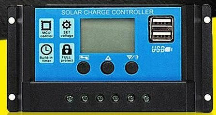
Control
As the single unit will absorb less energy from the sun, and also because the pump is solar powered, I only want the water to circulate through the heater when there is benefit in doing it.
The solar panel is linked to a solar battery changer and a very small lead acid battery. The charger has the capability to disconnect the load if the battery is discharged below a certain value, which protects the battery. The setup helps ensure a more “stable” voltage to the pump.
In addition, I have put together a small circuit using a thermistor, op-amp (comparator) and a MOSFET. The thermistor is attached to the head-spreader, under one of the small aluminum strips. When the temperature is high enough then the pump is turned on. This prevents the pool being cooled, and preserves solar battery power.

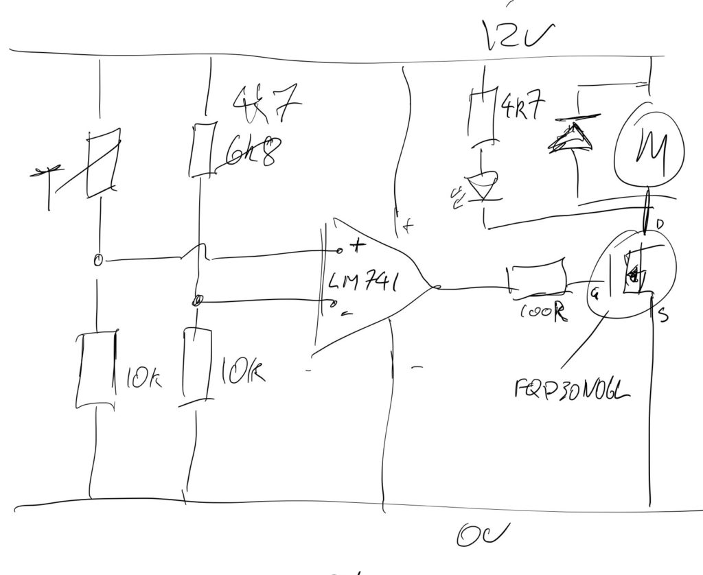
I used:
- 1 x LM741 or similar op-amp as comparator
- 2 x 10K resistors
- 2 x 4k7 resistors
- 1 x NTC Thermistor Temperature Sensor Waterproof Probe 25MM 10K 1% 3950 1m
- 1 x 100 ohm resistor
- 1 x random red LED
- 1 x N-Channel MOSFET, in this case N-Channel MOSFET, 32 A, 60 V, 3-Pin TO-220 ON Semiconductor FQP30N06L
- A fairly random diode possible 1N4004 for inductive load protection
You could put a variable resistor (10K?) in place of the resistor I’ve changed from 6k8 to 4k7 if you liked. Also a switch to short the thermistor could be useful for testing…
I built it on copper vero-board.
Automatic Air Bleed Value
I 3D printed this… it’s currently a work in progress, but it’s important to be able to vent air from beyond the pump – otherwise it will never prime. The current design leaks a little, but it does work.
I also created a small stand for it, to help keep it vertical.
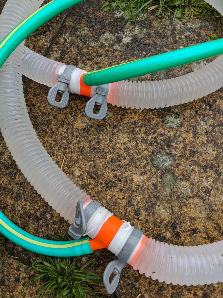
Pipe Joints
I also 3D printed these. As there are already pipes joining the pool to the filter pump, I made these to attach the solar heater in parallel with the filter pump. This makes priming the system a lot easier, and it’s a great deal neater than having to run additional hoses over the side of the pool.
The pipe joints are a sloped and ducted T joint, 2 x 32mm and 1 x 13mm. They should be closer to the pool than the filter/pump, otherwise the filter pump will circulate the water in the heater rather than the water in the pool.
The first prints were terrible, as the orientation of the print layers was inline with the joint – meaning that they leaked terribly. The second prints were better as the print layers were perpendicular to the joints – they still needed PTFE tape to get a good seal, but they work pretty well without any undue pressure.

Bringing It All Together